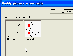
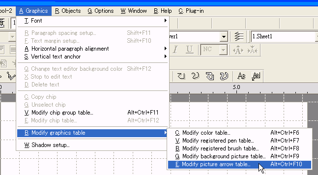
Click the menu [Graphics] > [Modify graphics table] > [Modify picture arrow table].

The [Modify picture arrow table] dialog will be displayed.
Push the [Add] button.

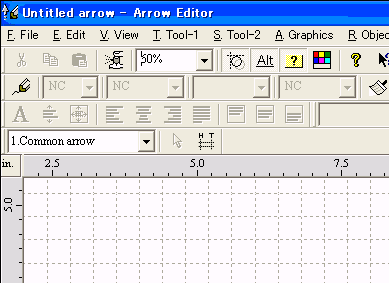
The Arrow Editor will be executed, and the window will be displayed.
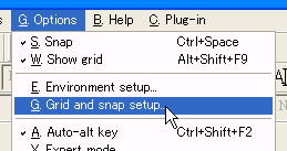
Click the menu [Options] > [Grid and snap setup].
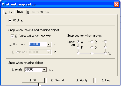
The [Grid and snap setup] dialog will be displayed.
Set 0.2 inches to snapping distance and push the [OK] button.
Activate the [Bezierline tool] command.
![]()
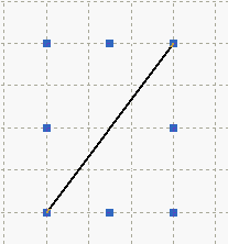
Draw a bezierline as illustrated in the following graphic.
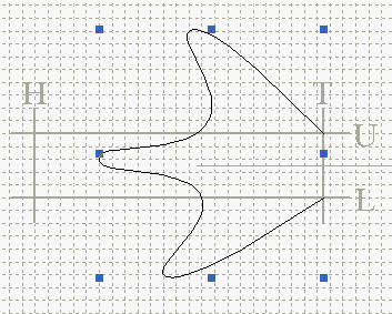
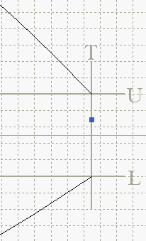
The beginning and ending point of the bezierline must be put on the T-U cross point and T-L cross point.
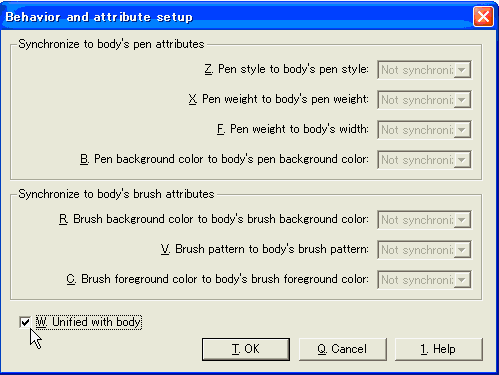
Select the bezierline and activate the [Object behavior setup] command.
![]()
The [Behavior and attribute setup] dialog will be displayed.
Tick off the [Unified with body] and push the [OK] button.
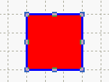
Activate the [Rectangle tool] command and make a rectangle.
![]()
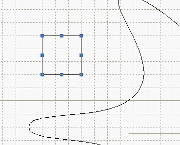
Change the pen and brush attributes and make a blue framed red rectangle as illustrated in the following graphic.
![]()
![]()
Duplicate the rectangle.

Select the new rectangle.
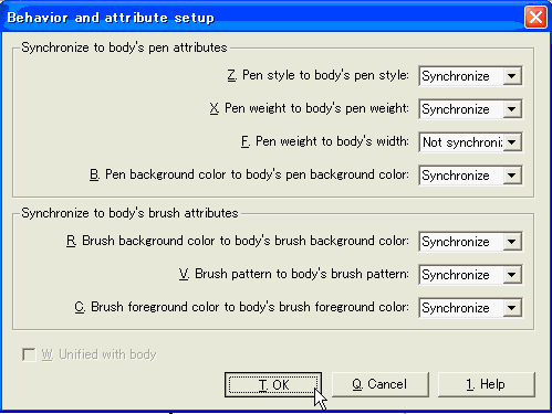
Activate the [Object behavior setup] command.
![]()
The [Behavior and attribute setup] dialog will be displayed.
Set each attribute like in the following graphic and push the [OK] button.
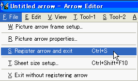
Click the menu [File] > [Register arrow and exit].
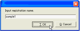
A dialog like the folloing will be displayed.
Input 'sample1' and push the [OK] button.
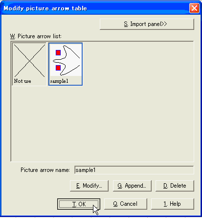
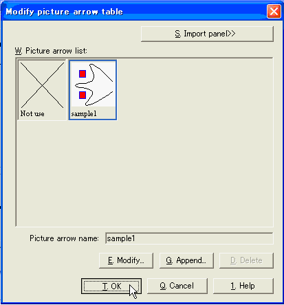
Make sure that the arrow has been added in the [Picture arrow list] and push the [OK] button.
Activate the [Line tool] command and draw a line.
![]()
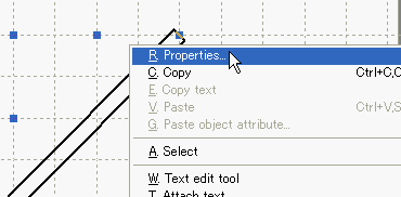
Right-click on the line.
A popup menu will be displayed. Then click the [Properties] command.

The [Properties] dialog will be displayed.
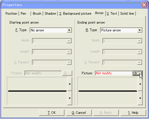
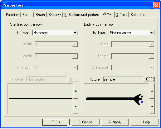
Choose the [Arrow] page.
Set 'Picture arrow' in the [Type] of the Ending point arrow.
And push the [...] button in the Ending point arrow.
[Modify picture arrow table] will be displayed.
Choose an arrow named 'sample1' and push the [OK] button.
Make sure that the arrow has been set in the [Picture] and push the [OK] button.

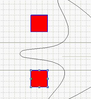
Change the pen and brush attributes of the line.
![]()
![]()
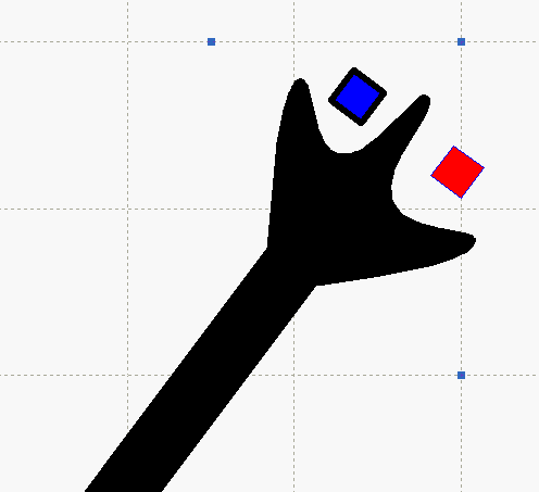
Make sure that one rectangle in the arrow is synchronized with the line attributes and another rectangle is not.
Activate the [Wide polyline tool] command and make a wide polyline.
![]()

Right-click on the wide polyline.
A popup menu will be displayed, then click the [Properties] command.
The [Properties] dialog will be displayed.
Choose the [Arrow] page.
Set 'Picture arrow' in the [Type] of the Ending point arrow.
And push the [...] button in the Ending point arrow.

[Modify picture arrow table] will be displayed.
Choose an arrow named 'sample1' and push the [OK] button.

Make sure that the arrow has been set in the [Picture] and push the [OK] button.
Change the pen and brush attributes of the wide polyline.
![]()
![]()
Make sure that one rectangle in the arrow is synchronized with the line attributes and another rectangle is not.

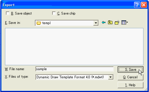
Click the menu [File] > [Export].
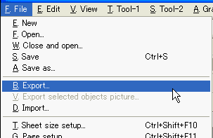
The [Export] dialog will be displayed.
Clear the [Save object] and [Save chip] checkbox.
Set 'Dynamic Draw Template Format 4.0' in the [File of type].
Set an appropricate folder to the [Save in] and input 'sample' in the [File
name].
Push the [Save] button.
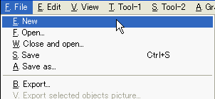
Click the menu [File] > [New].
A new Dynamic Draw will be run and the window will be displayed.
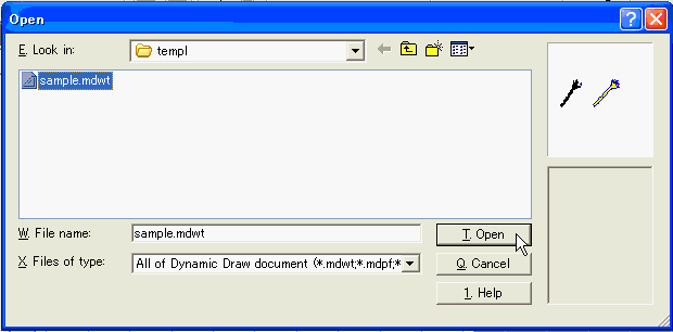
Click the menu [File] > [Import].
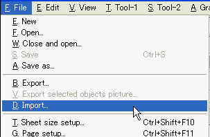
The [Open] dialog will be displayed.
Choose the last exported file and push the [Open] button.
Click the menu [Graphics] > [Modify graphics table] > [Modify picture arrow table].
Make sure that the arrow has been imported.