Start Dynamic Draw.
If the [Import template] dialog is displayed, click the Cancel button to
close it.
Confirm that the [Snap] and the [Auto-alt key] are activated.
If they are not activated, click them to activate.

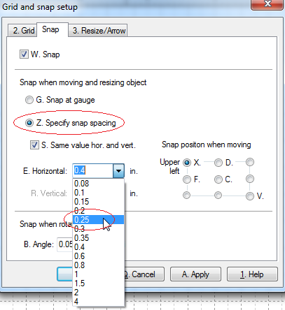
Click the [Options] > [Grid and snap setup] menu item.
Open the [Snap] tab page and choose 0.25 inch as the snap spacing.
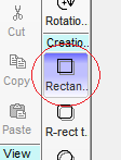
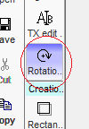
Type "SR" to activate the [Rectangle tool].
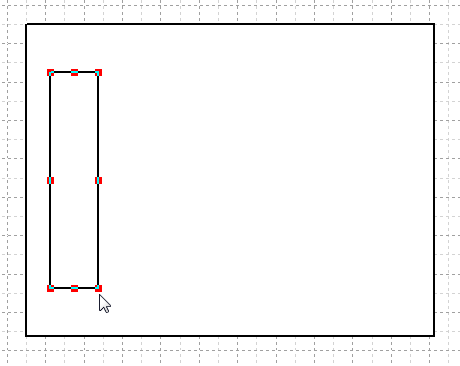
Hold down the left mouse button at the upper left area of the canvas.
Move the mouse pointer toward the bottom right direction, and release the
left button.
A rectangle will be created.

Make another small rectangle on the large rectangle.
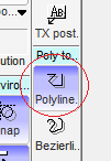
Activate the [Polyline tool].
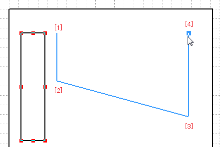
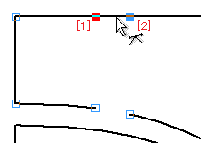
See the following graphic.
Click the left mouse button at the [1], to start the drawing.
Click the left mouse button at the [2], and the [3].
Finally, move the mouse pointer to the [4] and click the ESC key to complete
the polyline.
Click the [Objects] > [Properties] menu item.
Open the [Polyline] tab page, and choose [Close] as the [Both ends of polyline].
Click the [OK] button.

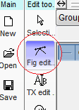
Activate the [Figure edit tool].
See the following graphic.
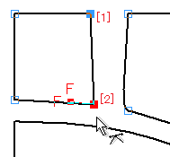
Select the joint [1] and [2].
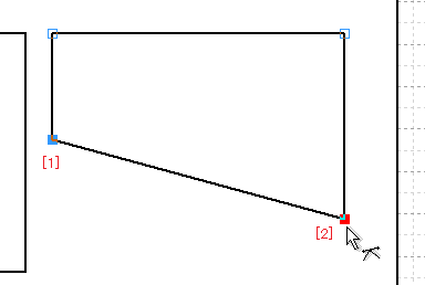
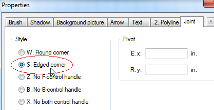
Click the [Objects] > [Properties] menu item.
Open the [Joint] tab page, and choose the [Edged corner] as the Style.
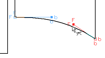
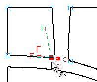
See the following graphic.
Drag the B-control handle and the F-control handle, to bow the bottom line.
After the dragging, click the ESC key to deactivate the [Figure edit tool].
Hold down the right mouse button on the polyline.
Drag it a small amount toward the bottom direction, and release it.
A popup menu will be displayed, then click the [Duplicate] menu item.

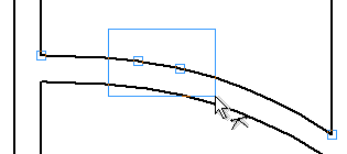
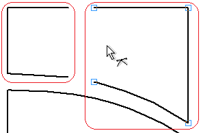
Activate the [Figure edit tool] and hold down the left mouse button on the line [1] in the following graphic, to select the upper left and upper right joint both.
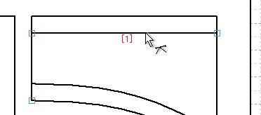
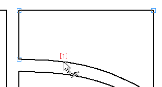
Move the mouse pointer toward the bottom direction and release the left mouse button to complete like the following graphic.

See the following graphic.
Select the polyline [1] and activate the [Figure edit tool].
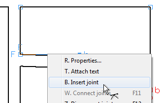
Click the right mouse button at the [1] and click the [Insert joint] menu
item, to insert a joint at the [1].
Insert another joint in the right of the [1].
Select those joints both.
Click the right mouse button on one of the joints, then click the [Disconnect joints] menu item.
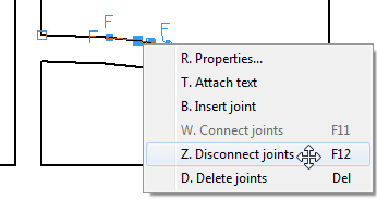
The joints will be disconnected.
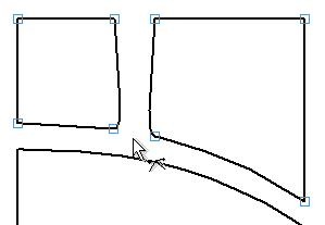
See the following graphic.
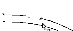
Insert joints at the [1] and the [2], and disconnect them in the same way.
As a result, the polyline has been split into two polylines.
Activate the [Selection tool].
Select the polylines both and click the right mouse button on one of the
polylines. Then click the [Modify object attribute] > [Connect joints]
menu item.

Activate the [Figure edit tool] again.
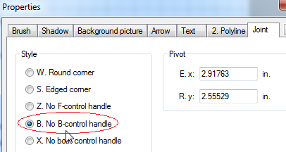
Select the joint [1] in the following graphic, then display the [Properties] dialog.
Choose the [No B-control handle] in the Style.
See the following graphic.
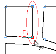
Select the joint [1] first. Then while the Shift-key pressed, click the
joint [2], to select both.
It's important that the joint [2] is selected at the last.
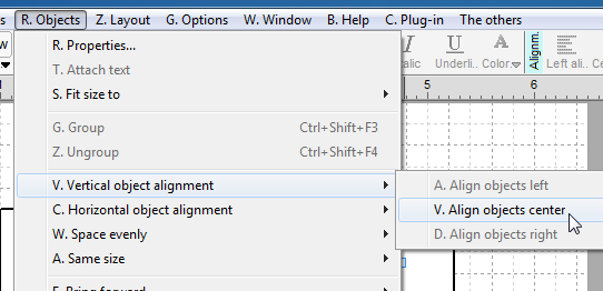
Click the [Objects] > [Vertical object alignment] > [Align objects center] menu item.
The joints will be aligned vertically. Confirm that the last selected joint is anchored.
Align the left two joints of the right polyline in the same way.
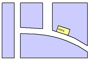
Color each object like the following graphic.

Locate a small rectangle and rotate it to follow the shape of the street.
See the follwoing graphic.
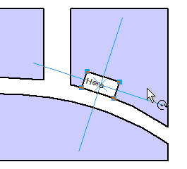
The map has been completed.