Choose [File] > [Import] from the top menu.
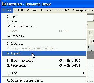
The [Open] dialog will be displayed.
Choose the file "C:\Program Files\Fukushiro Soft\Dynamic Draw5\Template\FlowchartEx.mdwt"
and click on the [Open] button.
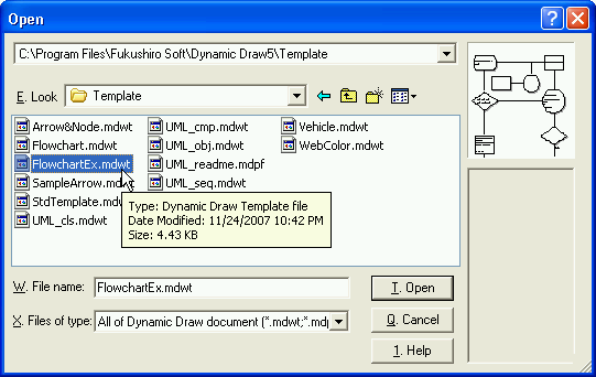
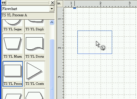
The template file "Flowchart.mdwt" will be imported and several
chips for flowchart will appear in the Chip Store.
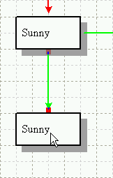
Hold down the left mouse button at the "TS_YL Process A" Chip;
then drag the chip into the Canvas and release the left mouse button.
As a result, a node object will be created.
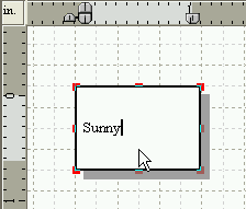
Activate the [Text edit tool] command in the toolbar.
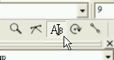
Type some text into the node object. For example, 'Sunny'; then click the 'ESC' key to deactivate the [Text edit tool] command.
Hold down the right mouse button on the object; then move the mouse pointer
bottom and release the right mouse button.
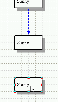
A popup menu will be displayed, then click on the [Duplicate] command.
It is ok to click with the right mouse button.
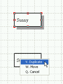
As a result, the node object will be duplicated.
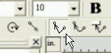
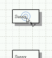
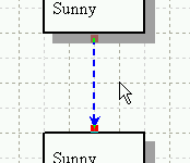
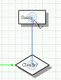
Activate the [Arrowed polyline tool] command in the toolbar.
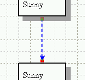
Stay the mouse pointer at the center of the node object.
When a double circle mark is displayed, click with the left mouse button.
Move the mouse pointer toward another node object.
Stay the mouse pointer at the center of the object.
When a double circle mark is displayed, click with the left mouse button.
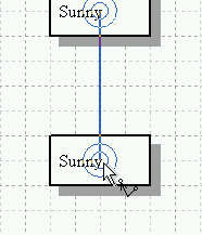
Two node objects will be connected by an arrowed polyline.
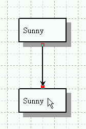
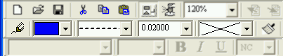
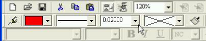
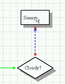
Using the pulldowns in the toolbar, change the pen color into blue, the pen style into dash-line and the pen weight into 0.02 inches.
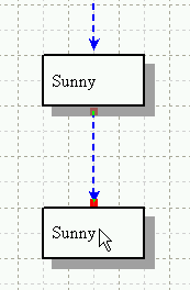
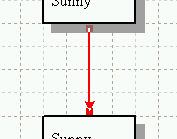
Duplicate and make another node object.
Activate the [Arrowed polyline tool] command in the toolbar.

Connect two objects with a new arrowed polyline.
Make sure that the new polyline has same attributes with the last created
polyline.
It is because that Dynamic Draw tries to refer to the last created object
when an
object is created.
The object refered is called "Reference Object".
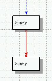
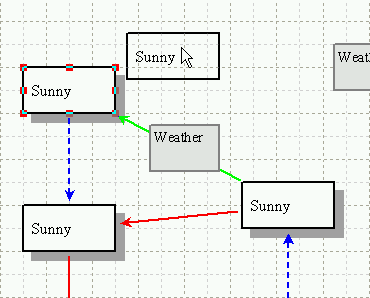
Using the pulldowns in the toolbar, change the pen color into red, the pen style into solid-line and the pen weight into 0.02 inches.
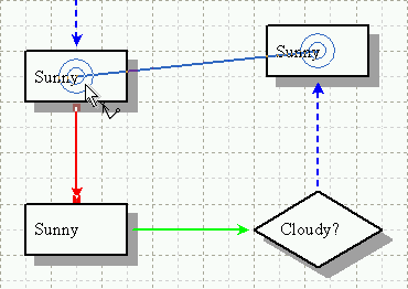
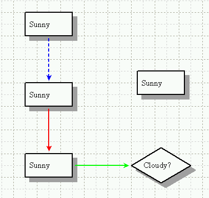
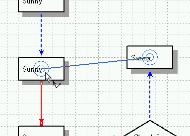
Make some other node objects and polylines as illustrated in the following graphic.
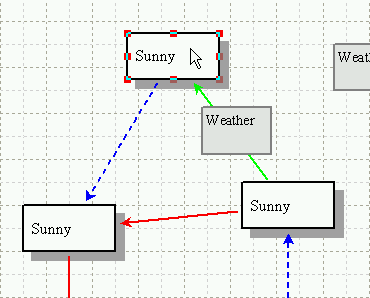
Select a blue dashed polyline.
Using the [Arrowed polyline tool] command, connect two objects with an arrowed polyline.
Make sure that the new polyline has same attributes with the selected polyline.
It is because that the selected object is treated as the Reference Object.
The selected object is prior to the last created object as a Reference
Object.
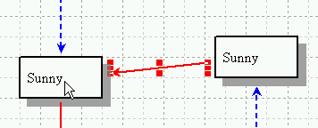
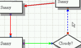
Select a red solid polyline.
Using the [Arrowed polyline tool] command, connect two objects with an arrowed polyline.
The two objects will be connected with a red arrowed solid polyline.
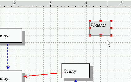
Make a rectangle object in the Canvas and type something like 'Weather' into it.
Activate the [Linked text posting tool] in the toolbar.
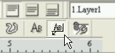
Stay the mouse pointer at the middle position of an arrowed polyline.
When a combination of a cross and a rectangle mark appears, click with
the left mouse button.
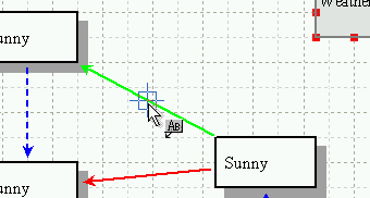
As a result, a rectangle object will be created refering to the last selected
rectangle object.
Click the 'ESC' key to deactivate the [Text edit tool] command.

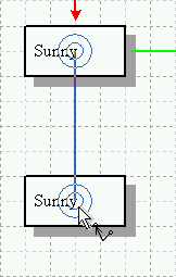
Move the node object that is connected with the rectangle attached polyline.
Make sure that the connected polylines follow the object and the attached rectangle follows the polyline.
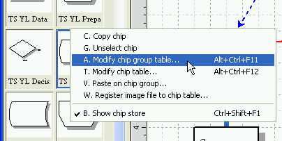
Click the Chip Store area with the right mouse button.
A popup menu will be displayed, then click on the [Modify chip group table]
command.
The [Modify chip group table] dialog will be displayed.
Click on the [Add] button to add a new group.
Click on the [OK] button.

Select three polylines: a blue, a red and a green one.
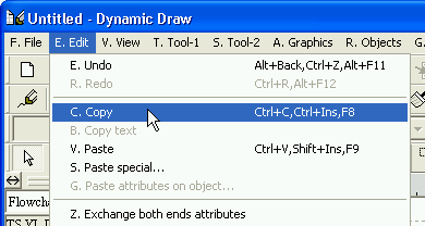
Choose [Edit] > [Copy] from the top menu to copy these three polylines.
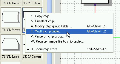
Click the Chip Store area with the right mouse button.
A popup menu will be displayed, then click on the [Modify chip table] command.
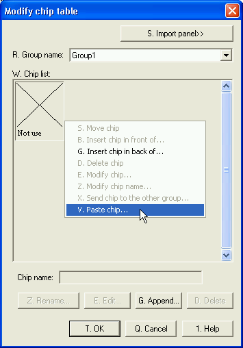
The [Modify chip table] dialog will be displayed.
Change the Group name into 'Group1'; then click the Chip list area with
the right mouse button.
A popup menu will be displayed. Then click on the [Paste chip] command.
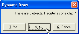
The following dialog will be displayed.
Click on the [No] button.
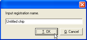
Chip Name inputting will be required three times with the following dialog.
Just click on the [OK] button three times at the each dialog.
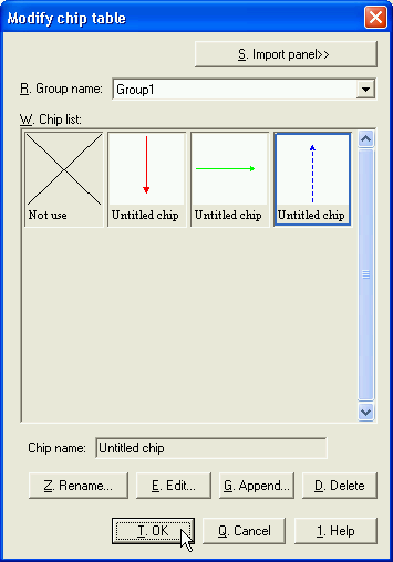
Three polylines will be registered as illustrated in the following graphic.
Click on the [OK] button.
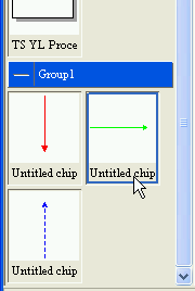
Click the green solid polyline chip in the Chip Store.
Confirm that any object in the canvas is not selected and make an arrowed polyline using the [Arrowed polyline tool] command.
A new polyline will be created and it has same attributes with the selected
chip.
It is because of the Reference Object.
The default priority of the reference is following :
'Selected object' > 'Selected chip' > 'Last created object' >
'Tool inside object'.
If you wish to change the order, click with the right mouse button on the
[Arrowed polyline tool] in the toolbar and click on the [Tool properties]
command.